

Chimney & Flue Design
The construction and application of chimneys and flues is covered by UK Building Regulations in conjunction with the relevant European and British Standards. Whilst these differ in emphasis, they all mandate the safe application of the chimney no matter where and how used. These Regulations and Standards dictate the minimum criteria which it is necessary to apply if the chimney or flue is to function safely and correctly.
Following BREXIT, the UK government introduced the UKCA mark with the intention of replacing the CE mark. It has now been decided that the CE mark continue for construction products but the use of the UKCA mark is not ruled out at a later date.
Since the publication of Document J in 2010, the National Annex to BS EN 15287-1 has been updated. The updated advice from the annex has been included in this document and will be highlighted in a blue shaded box.
It is important to match the internal diameter of the flue with the outlet on the appliance. It should never be less than the outlet diameter of the appliance. The appliance manufacturer’s chimney sizing recommendations should always be followed. For free-standing stoves, boilers and cookers up to a maximum of 20KW, that are not in a fireplace recess, the minimum flue size is 125mm round or square if the appliance has passed the DEFRA requirements for smokless zones and 150mm if this is not the case.
For open fires with a standard fire opening up to 500mm wide by 550mm high the minimum required flue diameter is 200mm round or 175mm square. For larger open fires, such as inglenooks, dog grate installations or special appliances and stoves designed to operate with a fire opening greater than 500mm x 550mm, the flue size should be at least 15% of the free unobstructed area of the fire opening (including sides if open). Many Decorative Fuel Effect gas fires (DFE's) that imitate a coal or log burning open fire require the same chimney arrangement as for solid fuel open fires and must be installed in accordance with British Standard BS5871:Part 3:2005
Under the new BS EN 15287-1 the guidance has been amended as follows:
Chimneys serving an appliance recess
For a chimney built with a fireplace recess in which an open fire, a room heater or stove may be fitted size a flue of 200 mm diameter or rectangular/square flues having the same cross-sectional area and a minimum dimension not less than 175 mm diameter. These flue sizes are suitable for virtually all closed appliance and for open fires with an opening up to 500 mm by 550 mm. For larger sizes of open fire, or closed app that can be used as an open fire, the cross-sectional area of flue should be 15 % of the free, unobstructed area of the fire opening.
In cases where a closed appliance, such as a room heater, boiler or cooker, is installed with a chimney intended for an open fire and built as recommended by BS EN 15287-1, it should not normally be necessary to make any alterations to the chimney or flue. If, however, the type and rating of the appliance to be installed is known before the chimney is built and it is unlikely that the chimney will be used for some form of open fire inset or free-standing, then the optimum size of the chimney can be determined for the particular installation.
Chimneys not serving an appliance recess
(recommended sizes of flue according to the table below)
| Installation (1) | Minimum flue size |
| Fireplace with an opening of up to 500mm x 550mm | 200mm diameter or rectangular/square flues having the same cross-sectional area and a maximum dimension not less than 175mm |
| Fireplace with an opening in excess of 500mm x 550mm or a fireplace exposed on two or more sides | If rectangular/square flues are used the minimum dimension should not be not less than 200mm |
| Closed appliance of up to 20 kW rated output which: a) burns smokeless or low-volatiles fuel (2) or b) is an appliance which meets the requirements of the Clean Air Act when burning an appropriate bituminous coal (3) or c) is an appliance which meets the requirements of the Clean Air Act when burning wood (3) |
125 mm diameter or rectangular/square flues having the same cross-sectional area and a minimum dimension not less than 100mm for straight flues or 125mm for flues with bends or offsets |
| Pellet burner or pellet boiler which meets the requirements of the Clean Air Act (3) | 125 mm diameter This may be reduced to no less than 100 mm when permitted by the appliance manufacturer and supported by calculation according to BS EN 13384-1:2002. This calculation can be applied to an individual installation or manufacturers can provide precalculated designs. |
| Other closed appliance of up to 30 kW rated output burning any fuel | 150 mm diameter or rectangular/square flues having the same cross-sectional area and a minimum dimension not less than 125mm |
| Closed appliance of above 30 kW and up to 50 kW rated output burning any fuel | 175 mm diameter or rectangular/square flues having the same cross-sectional area and a minimum dimension not less than 150mm. |
NOTE 1: Closed appliances include cookers, stoves, room heaters and boilers.
NOTE 2: Fuels such as bituminous coal, untreated wood or compressed paper are not smokeless or low-volatiles fuels.
NOTE 3: These appliances are known as ‘exempted fireplaces’.
It is important that there is easy access for cleaning, particularly at any change of direction in the flue. This can be achieved with the use of swept elbows that incorporate both debris collection and an inspection point.
It is worth noting that in SAP the assumed standing air loss for a flue with an internal diameter of 200mm and above is 40 cubic meters per hour. With a flue diameter of less than 200mm the ventilation rate is halved to 20 cubic meters per hour. This can have a significant impact on the energy rating of a house.
SAP is the Standard Assessment Procedure used to calculate the overall energy efficiency and carbon output of a house.
One of the keys to a well performing chimney is consistent insulation along the complete length of the flue. Clay/ceramic, concrete and pumice liners require insulation to be prepared and added on site. Stainless steel and ceramic system chimneys are supplied with effective insulation. Double wall pumice chimney systems have an air gap between the walls of the inner and outer block. The air gap combined with the natural insulating properties of pumice provide effective insulation along the length of the chimney.
SAP is the Standard Assessment Procedure used to calculate the overall energy efficiency and carbon output of a house.
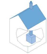
The ideal location for a chimney is on the inside of the building. That way it can benefit from being kept warm. Chimneys situated outside the building can be affected by cold weather causing poor up draught and condensation, particularly if they are un-insulated. It is therefore important that a cavity wall is continued around a lined masonry chimney or a factory made insulated chimney system is used for external applications.
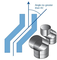
Both the Regulations and the Standards recommend that bends in the chimney be avoided, as a straight vertical chimney performs better. If bends are necessary there must be no more than four in the length of the chimney. The angle of the bend should be no greater than 45° from the vertical, with the exception that 90° factory made bends or tees may be treated as being equal to two 45° bends. Where System Chimneys are used, always use the standard offset components which are available from the chimney manufacturer. For stainless steel chimneys, certified to BS EN 1856, the distance between bends must be no greater than 20% of the total chimney length. It is recommended that a vertical rise of 600mm should be allowed immediately above the appliance before any change of direction. An inspection hatch is required between each offset.
It is important that there is easy access for cleaning, particularly at any change of direction in the flue. This can be achieved with the use of swept elbows that incorporate both debris collection and an inspection point.
Stoves, cookers and boilers should be connected to the chimney using correctly sized metal steel flue pipe which conforms to BS EN 1856-2:2009, or with alternative materials identified by Building Regulations such as Vitreous Enamelled flue pipe certified to BS 6999:1989.
Under the new BS EN 15287-1 twin wall stainless steel system chimney certified to BS EN 1856-1:2009 can be connected directly to the appliance.
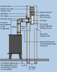
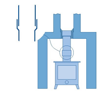
When a single wall connecting flue pipe is used to connect an appliance to a twin wall chimney, the new version of BS EN 15287-1 requires that the lower end of the twin wall chimney section must extend a minimum of 425mm below the ceiling. The flue pipe connection to the twin wall chimney must be made in the same room as the appliance.
The connecting flue pipe must be suitably sealed with spigot end facing down (into the socket of the pipe below). As excessive bends and horizontal runs can accumulate soot with the risk of blockage, the flue pipe should be kept as vertical as possible and the angle of bends should be no more than 45° from the vertical. In the current Document J the maximum horizontal length of flue pipe allowed from the back of an appliance into any chimney is 150mm. It is important that there is easy access for cleaning, particularly at any change of direction in the flue.
Alternative method of installation
In the new version of BS EN 15287-1 the maximum horizontal distance has been increased to 450mm so long as.
| - | A Defra exempt appliance or an appliance, which is limited to burning authorised smokeless fuel only, is installed. |
| - | A calculation according to BS EN 13384-1 has indicated safe operation of the proposed configuration, and the results of the calculation are left with the householder along with the appliance installation instructions. |
| - | The chimney manufacturer and appliance manufacturers agree in writing to the proposed configuration. |
| - | The total length of single wall connecting flue pipe is not more than 1.5m. |
| - | The appropriate distances to combustible materials from both the appliance and the connecting flue pipe are maintained. |
It is important that there is easy access for cleaning, particularly at any change of direction in the flue. This can be achieved with the use of swept elbows that incorporate both debris collection and an inspection point.
For open fires a suitable throated front lintel and gather must be installed above the fire opening, so that the front, back and sides slope up smoothly into the flue opening in the chimney at an angle no greater than 45° from the vertical. Flat surfaces or shelves must be avoided as these can cause turbulence and smoky fires. Most flue and chimney manufacturers provide standard gather and fireplace components. Precast fire chambers or Firechests are also available for standard and larger fire openings.
Some appliances, such as free-standing stoves and inset fires, have built in gathers or removable baffle plates to allow sweeping through the appliance. Building Regulations require that the connecting pipe is easily accessible for regular inspection and sweeping to prevent blockage. If this is not possible through the appliance, a purpose made access/soot door must be provided in the chimney. Most chimney manufacturers can provide components to suit. Where the connecting flue pipe goes into the side of the chimney a space must be provided with soot door access below this point to collect debris, such as soot, that may fall down the chimney.
There are many types of chimney pots and terminals, in different styles and shapes to suit almost any taste and application. However, it is important to ensure the chosen pot or terminal does not restrict the exit of the products of combustion. The area of the outlet must be at least the same as the flue area. If the terminal has a hood the area of the outlet should be twice the flue area. Beware of terminals which are primarily designed for ventilating a chimney where the fireplace has been closed off.
An open termination is normally recommended for wood burning and multi-fuel appliances. However rain caps or anti-downdraught terminals may be used. Rain caps and anti-downdraught terminals are available in two versions, with anti-bird mesh and without mesh. Where a terminal with mesh is used, there is a risk of soot build up, and therefore regular cleaning is required to avoid blockage.
If there is a “down draught” from the chimney (i.e. smoke blown back into the room) it is best to check that there is nothing wrong with the chimney arrangement, before fitting a special terminal. The problem is often caused by factors such as lack of ventilation in the room, poor throating above the open fire or insufficient chimney height.
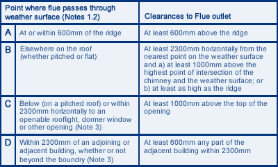
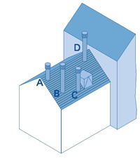
The minimum chimney height recommended for minimum performance of wood burning and multi fuel appliances is 4.5 m from the top of the appliance to the top of the chimney. It is best to position the chimney, so that it goes straight up as near to the roof ridge as possible. The diagram below, taken from Document J, shows the minimum flue discharge heights and positions for all wood burning and multi fuel applications. In some cases, particularly when chimneys are towards the bottom of a sloping roof or at the eaves, it may be necessary to increase the chimney height above these minimum mandatory requirements. The reason for this is to clear pressure zones created by wind hitting the roof and nearby structures, like trees, which may interfere with the up draught required by the appliance or fire. The maximum freestanding stack height above the roof for a traditional masonry chimney is 4.5 times the narrowest horizontal part of the chimney. In the case of stainless steel system chimneys, the manufacturer’s installation instructions should be consulted; however in most cases it will be around 1.5 metres. This measurement is taken from the last point where the chimney stack passes the through or past the edge of the roof up to the chimney capping or termination. Tall chimneys may need bracing, always consult the manufacturer for advice.
These require special attention and should only be worked on by experienced installers. Attention is drawn to the HETAS guide on thatched properties. The home owner’s insurance company must be advised of proposed works.
The use of electrically powered fans to assist natural chimney draught is a subject that must be discussed with both the fan supplier and heating appliance manufacturers who will normally provide technical advice to ensure safe operation. Even in the event of fan failure, the products of combustion must still be able to safely evacuate the chimney, in accordance with BS EN 15287-1. The products of combustion will continue to be produced until the appliance is extinguished.
All heating appliances need air to work efficiently and safely. It is essential that the appropriate permanent air supply, as required by the appliance manufacturer and Building Regulations is provided into the room where the appliance or open fire is situated. Always refer to the appliance manufacturer’s recommendations and Building Regulations before installation. An inadequate supply of combustion air can create problems. Situations assumed to be “down draught” and spillage of smoke and fumes back into the room, which can be unpleasant and dangerous, are more frequently caused by insufficient provision of combustion air. Either the openings have not been provided, are not large enough or have been simply blocked off. If the appliance does not get all the air it needs to burn the fuel efficiently, incomplete combustion will occur resulting in the production of carbon monoxide and, if badly deprived of air, copious volumes of soot.
All wood burning and multi-fuel appliances should have a carbon monoxide alarm fitted within the same room as the appliance. The carbon monoxide alarm should comply with BS EN 50291-1:2010, and must be installed to the manufacturers’ installation instructions, and current Buildings Regulations.
An alarm is required because carbon monoxide is a dangerous odourless and invisible gas.